Features
How to create shapes in CAD from polygon data in STL file format

This article outlines reverse engineering technology for creating shape data that can be used in CAD from data (point clouds or polygon data) collected with a 3D scanner (non-contact measurement device).
Images of creating shapes in CAD from collected point clouds (reverse engineering)
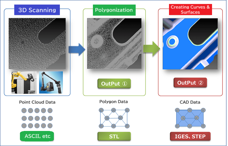
The images of reverse engineering that we discuss here are shown below.

Point Cloud Data
A set of data points with 3D spatial coordinate (x, y, z) position information.
Some point clouds now include information about the surface colors of an object using RGB color spaces.
Polygon Data
A polygon is a plane figure with a finite number of sides. In reverse engineering software, polygons are represented as triangular polygons (a plane figure with three vertices).
Polygon data can be created from point cloud data. When creating polygon data, polygons have the following tendency: the smaller the allowable deviation, the smaller the created polygons will be, while the larger the allowable deviation, the larger the created polygons will be.
In general, polygon data contains fewer vertices than point cloud data. Therefore, the amount of polygon data is smaller than that of point cloud data.
In some cases, polygon data is created from point cloud data using software on a 3D non-contact measurement scanner.
CAD Data
CAD is the abbreviation for “Computer Aided Design.”
CAD data is digital data generated by a computer-aided drawing system.
There are two types of CAD data: 2D CAD data and 3D CAD data.
2D CAD data is the data of flat shapes drawn in two dimensions, and 3D CAD data is the data of cube shapes drawn in three dimensions.
Reverse engineering software often creates polygon data as 3D CAD data because polygons are 3D shapes. It can also create 2D CAD data from 2D sectional curve information obtained from the information on 2D lines or cross sections created by projecting the boundary silhouette of polygon data onto a plane surface.
In some cases, a general CAD system may not be able to import a large point cloud dataset with many elements and data. Therefore, reverse engineering software temporarily creates curves and surfaces from point cloud data or polygon data and then outputs them in CAD standard format, allowing the CAD system to import them.
The output CAD data of curves and surfaces can be imported into popular CAD systems for use in CAD design or other purposes.
Reverse Engineering Techniques
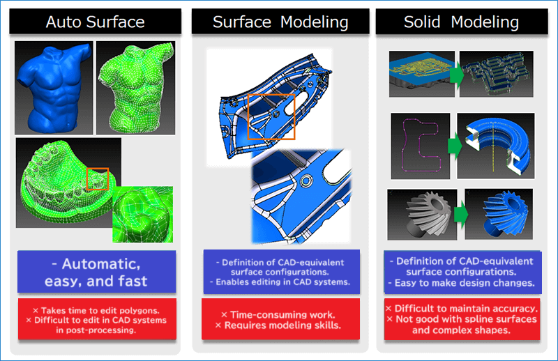
Reverse engineering techniques can be roughly divided into the following three types:
Select the appropriate technique for the application or system in which you will use the CAD data created by reverse engineering.

Auto Surface
Advantages
Generally faster reverse time.
Creation of complex spline surface shapes with ease.
Smaller deviations between polygons and reverse-engineered surfaces (deviations are likely to occur at sharpened edge parts).
Automatic creation of surfaces (but difficult to create complex shapes automatically).
Disadvantages
Editing polygons with many holes or irregular shapes tends to take a long time because the time required to edit depends on the shape of the polygon.
Editing in CAD is difficult due to the four-sided surfaces, which is not a common CAD surface composition.
Examples of applications
In general, this technique can be used for tasks that do not require editing of the surfaces created by reverse engineering in CAD.
・Reverse engineering related to craft works or medical products.
・Creating models for 3D printers.
It can also be used if you want to create surfaces in CAD first. (Remodeling with another CAD will be necessary in post-processing.)
・Departments that cannot devote man-hours to reverse engineering, such as inspection departments responsible for measurement and reverse engineering.
・Departments that need to easily create surfaces in CAD for delivery to a post-process modeling department.
・Many public facilities, such as industrial inspection centers, for simple reverse engineering.
Surface Modeling
Advantages
Capable of creating models with a surface configuration equivalent to CAD modeling (reference surfaces and fillets).
Capable of healing or making changes based on the shapes of surfaces created by reverse engineering in a CAD system.
Capable of creating reverse-engineered surfaces that take into account (specified) deviations from the polygons.
Disadvantages
Tends to take a long time to create surfaces by reverse engineering (improved functionality and usability have reduced man-hours).
Requires modeling skills to determine an appropriate surface configuration (automated determination capability is under development).
Examples of applications
Reverse-engineered shapes are used for CAD design, CAM (NC machining), data creation, and CAE analysis.
Reverse engineering for industries that handle large numbers of spline surface shapes, such as automotive (2-wheel or 4-wheel) related parts and molds.
Reverse engineering of automotive (2-wheel or 4-wheel) clay model designs.
Solid Modeling
Advantages
Capable of creating models with a surface configuration equivalent to CAD modeling.
Capable of healing or making changes based on the shapes of surfaces created by reverse engineering in a CAD system.
Capable of creating reverse-engineered surfaces using primitive elements (surfaces, cylinders, cones) with specified dimensions.
Capable of creating reverse-engineered 3D surfaces from 2D shape curves using features such as extrusion or rotation.
Disadvantages
Deviations from polygons are likely to occur.
Difficult to reproduce spline surface shapes.
Tends to take a long time to create surfaces in reverse engineering.
(Comparison of Reverse Engineering Time: [Auto Surface] < [Solid Modeling] < [Surface Modeling])
Requires modeling skills to determine an appropriate surface configuration.
Examples of applications
Applications where reverse-engineered shapes need to be drawn by specifying their dimensions during the design process in CAD.
Reverse engineering for industries that handle a large number of solid shapes, such as die casting, forging, or plastic products.
