Features
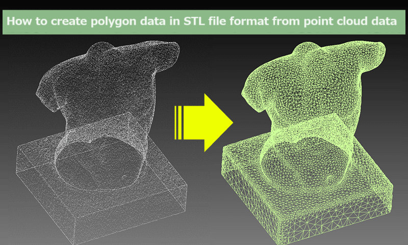
How to create polygon data in STL file format from point cloud data

This article provides an overview of the technique of polygonizing data (point clouds or polygon data) collected with a 3D scanner (non-contact measurement device) using reverse engineering software.
Polygonizing collected point cloud data
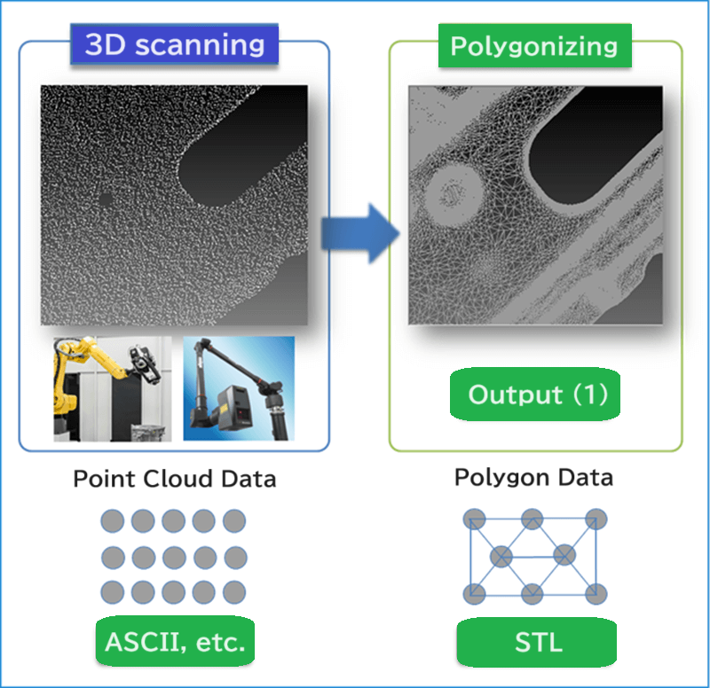
Images of polygonizing are shown below.

Polygon Data
A polygon is a plane figure with a finite number of sides. In reverse engineering software, polygons are represented as triangular polygons (a plane figure with three vertices).
Polygon data is created from point cloud data collected with a non-contact measurement device. When creating polygon data, polygons have the following tendency: the smaller the allowable deviation, the smaller the created polygons will be, while the larger the allowable deviation, the larger the created polygons will be.
In general, polygon data contains fewer vertices than point cloud data. Therefore, the amount of polygon data is smaller than that of point cloud data.
In some cases, polygon data is created from point cloud data using software on a 3D non-contact measurement scanner. In these cases, a fine pitch is often used to polygonize and export the data with the measuring device to reproduce the scanned data at a high resolution. This will often increase the data volume unnecessarily and cause the system to take a long time to perform processing or functions such as data import, view operation, reverse engineering, etc., making the data difficult to handle.
In addition, setting a fine pitch for polygonization may result in the reproduction of STL file data containing irregular surface shapes, which is one of the sources of noise in scanned data and is not originally present in the product shapes, producing an unintended result.
We recommend that you determine the resolution of polygons based on the resolution of the image you want to reproduce and the accuracy of the measuring device you are using.
With our software “spAlign (spGauge),” you can repolygonize the fine-pitch polygons in an STL file exported from a 3D scanner by specifying the resolution required for the reproduction.
Examples of settings for polygonizing scanned data collected with a 3D scanner using spAlign (spGauge)
Although the settings depend on the resolution and the surface irregularity obtained from the original data, the following settings are generally used for press molds and panels.
- For scanned data of camera-type 3D scanners
- Scanning press molds: 0.005 to 0.01 mm
- Scanning press panels: 0.05 to 0.1 mm
- For scanned data of laser-type 3D scanners
- Scanning press molds: 0.05 to 0.1 mm
- Scanning press panels: 0.05 to 0.2 mm
- Scanning press molds: 0.05 to 0.1 mm
Comparison of resulting images with different resolutions set with spAlign (spGauge)
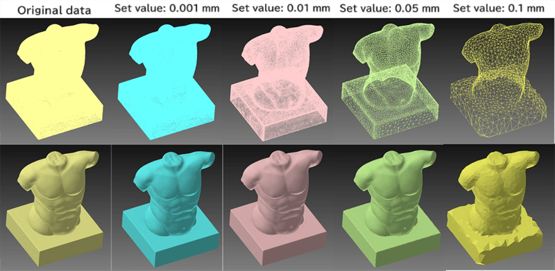
We compared the resulting images by focusing on the difference in the resolution set for polygonization. Please take a look.
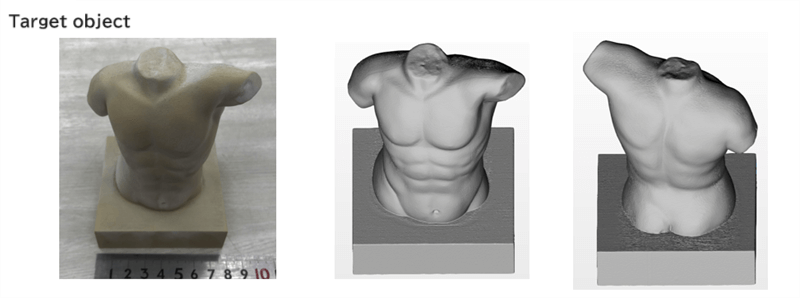
A camera-type 3D scanner was used. The target object was a replica of a plaster figure produced by a 3D printer, and its dimensions were approximately 100 × 120 × 120 mm. The resulting images from the data were compared.
The STL file of the polygon data was downscaled to some extent by the 3D scanner. A further reduction was achieved by setting the polygonization resolution to 0.001 mm. The data volume was reduced from 60.7 to 44.6 MB.

The higher the set resolution, the larger the polygon size and the smaller the volume of polygon data became. At that time, the original data could be polygonized within the specified resolution. However, if the specified resolution is too high, the reproducibility of the original shapes will deteriorate. Based on the results of this test, 0.01 and 0.05 mm are recommended for the set values.
Polygonized Shapes and Polygon Sizes

Color mapping that represents deviations between the original data and polygonized data, deviation distribution graph display

Summarized data on comparison results

Polygon Data Edit Feature
For information on how to edit the polygonized data in STL files, see the “Edit defective areas of the polygon mesh” page below.
